CRV - Constrained Random Verification
Verification is the critical bottleneck in the development process of modern digital logic circuits. In case of large ASIC or FPGA designs verification takes 70% of the total development time. EDA (Electronic Design Automation) vendors try to solve this issue providing tools for speeding-up verification process and ensuring high verification quality by covering entire design functionality with detailed tests. Verification methodology based on pseudo random generation has been used since many years especially in telecommunication and other areas of electronic industry. Both VHDL and Verilog do not really support random generation. The previous pseudo random testbenches commonly used PLI or other C interfaces available in HDL simulators to model random generations. Today, constrained random verification is supported in several modern verification languages. It can be used now by verification engineers in a more systematic and formalized way. The following solutions for constrained random verification can be found on the market:
-
SystemC SCV - free C++ library providing necessary classes to build testbench with pseudo-random generation.
-
SystemVerilog - new verification and hardware description language, which is an extention of Verilog-HDL. It supports constrained random verification. Provided in Aldec, Mentor Graphics or Synopsys tools.
-
SpecMan eTM - new verification language provided by Cadence. It is unique aspect oriented language available on the market.
-
VeraTM - provided by Synopsys. It is generally object oriented verification language. VeraTM has similar syntax to C++.
It is hard to guess, which of the above solution is the best. However, SystemVerilog may become the most popular language because of its backward compatibility with Verilog-HDL. There are also plans to extend VHDL language with constructs supporting pseudo random generation.
Architecture of a testbench with pseudo random generation is similar in all the above solutions. A User must define data structures, which represent stimulus applied to the tested unit. Next, constraints must be defined to guide the pseudo random generator. The contents of the data structures is generated by the pseudo random generator. However, the generator must always create valid stimulus for the tested unit. The stimulus must not violate protocols or other requirements defined in the interface specification. The constrains are used to guide pseudo random generation and create sequence of valid stimulus. Please, take a look at the figure below, which shows constrained random verification testbench architecture.
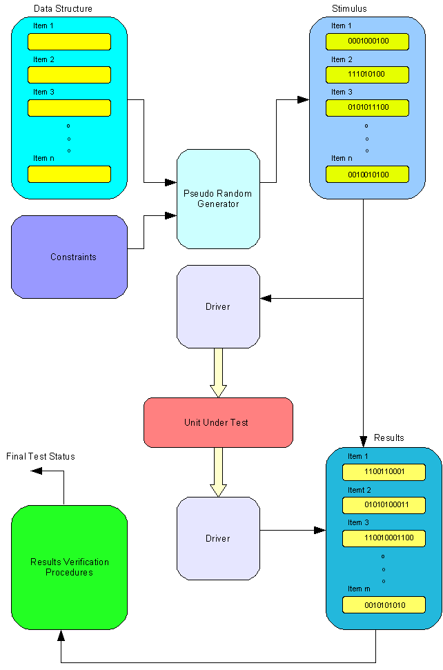 |
Next element of our testbench is a driver. It takes the stimulus from generated data structures and apply them to the tested unit according to its interface protocol. The driver is usually a bus functional model (BFM). For instance, it can be ARM AHB bus functional model, which generates write cycles and send data to unit under tests. Number of applied stimulus can be defined as the number of performed random generations. Here, we can see the power of the testbench with constrained random generation. Traditional directed testbench applies the set of stimulus written directly by a verification engineer. If the tested design is not fully covered the set of stimulus must be manually expanded with additional test procedures and test vectors. Moreover, verification engineers do not have possibility to define various scenarios of the directed testbench. The order of applied tests vectors is strictly defined in the testbench and cannot be changed. Separate testbenches must be written if several scenarios are required. Constrained random testbenches do not have such limitations. Different scenarios can be randomly generated. The stimulus are not strictly defined. They are generated and applied in a random order according to defined constraints. The generated sequences often exceed imagination of designers and verification engineers. In order to achieve full coverage the constraints and the number of random generations must be set correctly. Most of the modern verification tools provide also functionality to check coverage of the verified design. The coverage allows us to determine if the verified design if fully covered by our test or something is still untested. Usually, the constraints must be relaxed to cover the untested areas. There is also possibility to automatically measure the coverage and modify constraints in a loop increasing adaptively the coverage. It is rather difficult approach especially with large designs and it is not frequently used.
Stimulus generation is relatively easy comparing to results checking. The responses from the tested unit are read by a driver. The same driver is frequently used to apply stimulus and read responses. The driver stores responses in separate data structures creating results table. Unfortunately, we must write procedures or functions to check the results. The results checking functions and procedures are usually similar to some functions and procedures available in the tested unit. However, it cannot be the same code to avoid occurrence of the same bugs in the testbench and tested unit. Verification engineers spend most of their time on writing code for results checking. The code reads the results table and check if the results are valid. Finally, we get passed/failed status from the testbench. The results checkers are quite similar in both constrained random and directed testbenches. However, the stimulus generators are much more effective in case of constrained random testbenches. Summarizing, constrained random verification is the more suitable approach for today´s large digital designs. Constrained random testbenches achieve higher coverage than directed testbenches while consuming less development time.
|